1) After receiving the construction drawings, the project leader organizes relevant project technical personnel and quality personnel to carefully read the design drawings and relevant technical documents, clarify the design intent, engineering focus and difficulties, make technical preparations in advance based on referring to the manufacturer's information, and organize on-site technical personnel to conduct internal audits of the construction drawings, summarize the problems in the construction drawings, and propose their own handling suggestions, Please ask the design team to resolve the issue during the construction drawing review.
2) According to the characteristics of the project, site conditions, construction period requirements, and relevant document requirements, prepare the "Special Construction Plan for Seismic Isolation Engineering". Develop a special construction plan based on its requirements, combined with the characteristics of the project, construction conditions, and relevant technical requirements. The special construction plan prepared shall be submitted to the supervising engineer for approval before implementation. The approved technical documents shall be provided to the construction team and all construction personnel for technical disclosure and guidance on construction.
working procedure | Job type | Remarks |
Embed Installation | Measurement workers, welders, general workers, technical personnel | On site cooperation between surveyors, tower crane operators, signal workers, and other relevant personnel |
Support installation | Measurement workers, welders, technicians, and general workers | |
Note: The number of personnel is determined based on the actual situation of the project. | ||
Main Tools and Instruments Configuration Table
name | quantity | name | quantity |
Theodolite | Ink dou | ||
Level (Infrared) | Stone pen (chalk) | ||
Horizontal ruler | Electric welding machine | ||
Construction hammer | Hair dryer | ||
Steel tape measure | wrench | ||
Crowbar | Tower crane | ||
Car crane | forklift | ||
Note: The selection is determined based on the actual situation of the project. | |||
1) Verify whether the specifications, models, positions, and elevations of the isolation LRB on the design drawings are correct.
2) Before installing the support, sampling inspection should be carried out. Our LRB seismic isolation is 100% tested and can only be installed after passing the inspection.
3) Check whether the plane position, verticality, and height of the reinforcement cage for the lower pier meet the installation requirements.
4) Check whether the flatness of the positioning plate meets the installation requirements. If the deformation exceeds the standard, on-site correction is required.
1) Elevation control: Weld 4 short steel bars on the top surface of the lower pier in advance, with a diameter not less than 10mm. The top elevation of the short steel bars should be the design elevation of the lower pier (column). Pay attention to the fact that the top surface of the short steel bars must be cut flat. Use a level to check whether the 4 short steel bars are flat. Place the positioning plate on the top surface of the 4 short steel bars, and check the levelness of the positioning plate again with a level. Only after passing the inspection can the next construction proceed, If there is a significant deviation in the levelness, it should be checked and corrected to be qualified.
2) Center line (axis) control: The center line of the positioning plate coincides with the center line of the lower support pier in the plane, and there is no eccentricity of the positioning plate. Before installation, pop out the centerline of the positioning plate, use a cross engineering line to pull through the line or an infrared instrument to determine the position of the pier centerline. Place the positioning plate on the short steel bar surface, adjust the position of the positioning plate, and the cross centerline on the positioning plate coincides with the hanging cross engineering line (infrared) to determine the plane position of the positioning plate.
3) Levelness control: Check the diagonal levelness of the positioning plate with a level ruler. The level bubble is in the center.
4) Installation and fixation of anchor sleeve components: After the axis (centerline) and elevation control of the positioning plate meet the requirements, the anchor sleeve components are threaded into the lower pier reinforcement cage one by one, connected and fixed with bolts to the positioning plate. After fixation, the elevation, axis, and levelness of the positioning plate are checked, retested, and recorded. Check whether the top surface of the sleeve is flush with the positioning plate, and whether the anchor bars are vertical. After passing the inspection, use short steel bars to spot weld and fix them firmly with the main reinforcement of the lower pier.
5) Concealed acceptance: Before concealment, check the specifications, models, and positions of the positioning plate and anchor sleeve components one by one to ensure they comply with the design drawings. Only after passing the inspection can it be concealed. (Refer to the connection parameter table in the design drawings, where the dimensions and models of the isolation support, positioning plate, and anchor sleeve component correspond. For example, for a support with a diameter of 600, the size of the positioning plate is generally 700x700.).
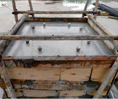
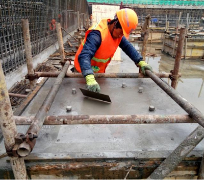
1) Lower pier pouring in one go: The concrete is poured into shape in one go, and the concrete is placed in the reserved hole in the middle of the embedded plate. During the concrete vibration process, it is strictly prohibited to collide with the positioning plate and anchor bars. It is prohibited to directly step on the positioning plate for vibration to prevent deviations in the axis, elevation, and levelness, which may affect the installation quality. After the concrete pouring is completed, the positioning plate should be taken out after the initial setting and before the final setting. The bolts should be re screwed into the sleeve, and the original slurry surface should be leveled and polished (checked for flatness with a horizontal ruler). The surface of the lower support pier should be slightly higher than the top surface of the sleeve. Then, the surface of the lower support pier should be retested and recorded, including elevation, center position, and levelness.


Pour concrete for the lower pier, take the slab, and use the original mortar to level and polish the surface
1) Grinding of the lower support pier: Check the surface levelness of the lower support pier with a spirit level, grind it flat with an angle grinder, clean the surface of the support pier and the debris inside the sleeve with a hair dryer, and the top surface of the sleeve should not be higher than the concrete surface of the lower support pier.
2) Model annotation: According to the design drawings, label the specifications and models of the isolation bearings on the surface of the lower support pier.
3) LRB seismic isolation installation: Choose lifting tools, such as tower cranes, truck cranes, gantry cranes, forklifts, and other lifting equipment. According to the design drawings, lift the corresponding support specifications and models into position, screw all bolts into the sleeves, and tighten the bolts symmetrically in two stages. Generally, the support connection bolts provided by our factory are 8.8 grade ordinary bolts with no torque requirements. If high-strength bolts are used in special projects, a torque wrench should be used to tighten them according to the initial torque, repeated torque, and final torque.
4) Model review: Refer to the design drawings and check each seismic isolation type and position one by one to ensure they are correct. Focus on reviewing the installation positions of lead rubber bearing (LRB) and lead-free bearing (LNR) of the same diameter, and avoid installation errors.
5) Installation inspection: Check the gap between the seismic isolation and the lower pier surface (flange plate and lower pier surface are closely attached), check whether the bolts are tightened, and copy the production number of the support on the nameplate (to be used when filling in information). When there are double supports, their height difference should be checked.
6) Upper construction: The upper anchor sleeve component is directly connected and fixed firmly with bolts to the upper flange plate.
7) Deformation observation: vertical compression deformation (net height of upper and lower flange plates), horizontal displacement (inclination) of upper and lower flange plates, and measurement of lateral uneven deformation (side bulge) base. The number of observations is once after the installation of the support is completed, half of the main body construction is completed, the main body is capped, and before acceptance, for a total of four measurements.