Earthquake-proof building design and how to choose the earthquake resistance products
key words :lead rubber bearing , Earthquake-proof building design, lead rubber bearing,seismic isolation, LRB, earthquake resistance products, isolation system, LRB designing
Earthquake resistance products are mainly used in the construction of buildings and bridges, earthquake resistance products plays a significant role in reducing the harm of earthquakes. Therefore, in recent years, many Earthquake-proof building have required the use of seismic products
1. Earthquake-proof building design

2. Selection of isolation layer position
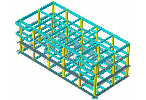
This project is located in a high seismic intensity area, and the seismic degree is 8 degrees (0.2g).The determination of the position of the isolation layer needs to consider multiple factors, including structural rality, cost economy, and functional layout rationality. For multi story structures, it is necessary and effective to adopt isolation technology to improve the seismic performance and economic efficiency of the structure. After comprehensive consideration, the height of the isolation layer is taken as 0.85m.
3.Seismic isolation design concept
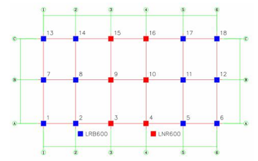
Due to the project location is in a high-intensity area ,and a seismic fortification intensity of up to 8 degrees, the layout diagram of the isolation bearings for Kindergarten A
As shown in the figure, the blue part represents LRB600 lead rubber isolation bearings, and the red part represents LNR600 rubber isolation bearings.

4.Composition of isolation system
The isolation system of this project mainly consists of rubber isolation bearings.
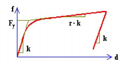
Lead rubber bearing is to add lead core in the rubber bearings,Improving Damping by Utilizing the Yield Hysteresis Dissipation Energy of Lead Core,
We can understand the lead rubber bearing as a combination of rubber and lead core,he rubber restoring force model adopts an equivalent linear model, while the lead core restoring force model adopts a viscous damping model. After combination, a bilinear model is formed,as bellow
5.The Seismic requirements
location | Top structure | Isolation layer support pier | Bottom structure |
Designing reqirement | The seismic action is confirmed based on the maximum horizontal impact coefficient ,after seismic isolation and reduction, and the seismic construction measures are confirmed based on the reduced value (not reduced for those related to the vertical direction) | Satisfy the load-bearing capacity verification of isolated structures when rare earthquake actions | The seismic action shall be determined based on the local level influence coefficient, and the seismic construction measures shall not be reduced. The embedded stiffness ratio shall be met, and the seismic bearing capacity shall be calculated after seismic isolation. The shear bearing capacity shall be verified according to rare earthquakes |
6.Analysis of seismic isolation structures
Analysis the seismic isolation structure, there are series of calculation and verification as bellow steps
1), Analysis model ,
2),Selection of seismic waves
3),Layout of isolation layer
4),Structural Period and Mode Analysis of Earthquakes
5),Calculation of wind bearing capacity and elastic recovery capacity of seismic isolation
6),Eccentricity verification of isolation layer
7),Calculation of compressive stress of lead rubber bearing under vertical loading
8),Seismic isolation analysis under earthquake action
9),Seismic isolation analysis under rare earthquake action

7.The arrangement of isolation layers (isolation bearings) should meet the following requirements:
(1) The isolation layer can be composed of isolation bearings, damping devices, and wind resistant devices. The damping device and wind resistance device can be integrated with the isolation support or can be set separately. If necessary, limit devices can be set.
(2) The stiffness center of the isolation layer should coincide with the mass center of the upper structure.
(3) The plane layout of seismic isolation bearings should be consistent with the plane position of the vertical load-bearing components of the upper and lower structures
(4) When selecting multiple specifications of isolation bearings for the same building, attention should be paid to fully utilizing the bearing capacity and horizontal deformation capacity of each rubber bearing.
(5) When multiple isolation bearings are used at the same support, the clear distance between the isolation bearings should be greater than the space requirements required for installation operations.
(6) The wind resistant devices installed on the isolation layer should be symmetrically and dispersedly arranged around or near the building.
(7) The vertical compressive stress of each rubber isolation bearing in the same isolation layer should be uniform, and the average vertical stress under the representative value of gravity load should not exceed the limit value of 12MPa for Class B buildings.
(8) Under rare earthquakes, isolation bearings should not experience tensile stress. When a few isolation bearings experience tensile stress, their tensile stress should not exceed 1MPa.
(8) Under rare earthquake action, the compressive stress of isolation bearings should not exceed 30MPa.