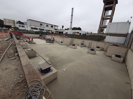
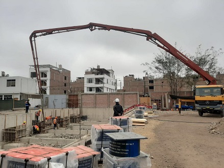
During the binding process of the upper pier reinforcement cage, on-site positioning plates can be used to reserve the position of the upper pier anchor bars in advance. Then, the upper pier reinforcement cage can be placed on the top surface of the support, and the upper embedded parts can be connected to the seismic isolation bearing with bolts.
Install the bottom form work of the upper pier in sequence, and the surface of the bottom forrm work should be level with or slightly higher than the top surface of the support. After the concrete pouring and demolding of the upper pier, the upper flange plate should be exposed. Pay attention to the reinforcement of the upper column, and direct anchoring can be used when the anchoring length is met.
Installation of upper pier reinforcement cage and formwork
Due to the inevitable damage and contamination of the paint on the flange plate of the isolation bearing during the installation process, template support, and removal process. After the construction of the isolation layer is completed and the formwork is removed, the paint on the flange plate of the isolation support is repaired and cleaned. The surface of the bolts is coated with butter to form a protective film and reduce later bolt corrosion.
(5).prevention measures for isolation bearings
When the LRB isolation bearing is installed in a space with fire resistance requirements, the is prevention measures for isolation bearings
ntion measures according to the fire resistance level of the space.
No. | Quality contoll points | inspection quantity |
1 | Specification, model, and location of embedded parts for positioning | ALL |
2 | Inspection of the elevation, plane position, and levelness of the lower pier | ALL |
3 | Installation position of supports (lead rubber bearing and lead-free of the same diameter) | ALL |
4 | Inspection of gap between flange plate and lower pier surface | ALL |
5 | Bolt tightening | ALL |
1) The distance between the positioning plate and the top surface of the main reinforcement of the lower pier is too large: (Generally, it is required not to exceed 50mm.)
Suggestion for handling: Place two layers of mesh reinforcement between 50mm and 100mm on the top surface of the main reinforcement, with a spacing of 50mm. exceed At 100mm, the main reinforcement of the lower pier needs to be extended.
2) The installation of the positioning plate is offset and not located in the center of the lower pier:
Suggestion for handling: Remove the positioning plate and sleeve anchor bar components and reinstall them.
3) The sleeve anchor bar of LRB seismic isolation component is tilted:
Suggestion for handling: Before fixing the anchor bars, check all of them one by one, align the top surface of the sleeve with the positioning plate, and ensure that the anchor bars are vertical. After reinforcement, it needs to be removed and re calibrated vertically before welding and fixing.
4) The plane deviation of the steel bars on the lower pier is significant, and the anchor bars are inserted on the outer side of the lower pier steel cage:
Suggestion for handling: Use planting tendons. Add hoop reinforcement to ensure that the anchor bars are inside the lower pier reinforcement cage.
5) The top surface of the sleeve of LRB is higher than the top surface of the lower support pier, and the concrete pouring of the lower support pier is not dense:
Suggestion for handling: roughen the surface of the lower pier and use epoxy resin or high-strength grouting material for secondary leveling.
6) The gap between the flange plate of the LRB seismic isolation and the surface of the lower pier is relatively large:
Suggestion for handling: Lift the support, re polish the lower support pier, and check the flatness of the lower support pier with a level until it is qualified.
7) The upper flange plate is not exposed, and the grounding wire is left improperly:
Suggestion for handling: During the installation of the formwork at the bottom of the upper pier, attention should be paid to controlling the elevation and position; The grounding wire should be reserved with a dedicated grounding wire and sufficient deformation should be reserved.
8) The LRB isolation joint is filled with hard materials:
Suggestion for handling: Remove the hard material and use flexible material filling or hollow outer board sealing.
9) The isolation layer is damp, with accumulated water and construction waste:
Suggestion for handling: Drain the accumulated water and clean up the garbage. Ensure that the isolation layer is dry and clean.
Quality acceptance of building isolation engineering
1. Product inspection and acceptance
LRB Isolation bearings should provide inspection data such as raw material qualification certificates, factory qualification certificates, type inspection reports, factory inspection reports, and third-party inspection reports when leaving the factory. Quality certification documents should be provided for embedded parts.
According to the sampling requirements of EN15129, for general buildings, the sampling quantity is not less than 20% of the total number. The inspection quantity of the building isolation rubber bearings provided by our factory is 100% to ensure that each isolation bearing passes the inspection before it can be used in the project.
(1) Product acceptance
1) Appearance quality of the LRB seismic isolation bearing
Defect name | Quality Standard |
bubble | The area of a single surface bubble does not exceed 50mm2 |
Impurities | The impurity area does not exceed 30mm 2 |
Lack of glue | The area of missing glue shall not exceed 150mm 2 and shall not be more than 2 places, and the internal insert shall not be exposed. |
uneven | The unevenness shall not exceed 2mm, the area shall not exceed 50mm 2 , and the area shall not exceed 3 places. |
The glue steel is not firmly bonded (upper and lower end faces) | The length of the crack shall not exceed 30mm, the depth shall not exceed 3mm, and there shall be no more than 3 cracks. |
Cracks (surface) | not allowed |
Exposed steel plate (side) | not allowed |
2) seismic isolation Bearing product size deviation
D ´ , a ´ and b ´ (mm) | Allowable deviation |
D ´ , a ´ and b ´≤500 | 5mm |
500< D ´ , a ´ and b ´≤1500 | 1% |
H | ± 1.5% and not greater than ± 6mm |
Check item | Allowed quality deviation | |
Center elevation of embedded parts (seismic isolation bearings) | ≤±5mm | |
Plane position of embedded parts (isolation bearings) | ≤±5mm | |
levelness | Top surface of embedded parts (lower buttress) | ≤5‰ |
Top surface of support | ≤8‰ | |
The height difference between two supports on the same pier | ≤5mm | |
Quantity of inspections: Full inspection. All embedded parts and isolation bearings must be inspected and accepted before entering the next process.
Maintenance unit: isolation building user unit, property management unit, construction unit, etc.
(4) Maintenance time
The maintenance phase begins from the date when the seismic isolation building passes the completion acceptance inspection.
Frequent inspection: During daily use, isolation products should be inspected frequently to detect problems in time and deal with them promptly.
Periodic inspections: 1, 3, 5, 10 years after completion, and every 10 years thereafter.
Inspection: arranged by the product manufacturer.
Emergency inspection: Inspection should be carried out immediately when encountering natural disasters such as earthquakes, floods, mudslides, fires, etc.
(5) Maintenance inspection items
Check item | Check content | Inspection Method |
logo | Is it clear and complete? | observe |
Connecting plates and bolts | Whether it is rusty or loose | Observation, wrench inspection |

